
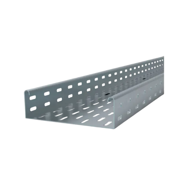
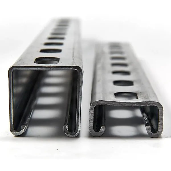
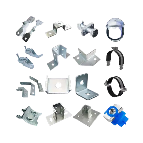
Cable support systems engineered for HV and MV substations, covering cable routing between transformers, GIS/AIS switchgear, control buildings, relay rooms, and outdoor yard infrastructure.
Designed to support high mechanical loads, maintain cable segregation, and ensure longterm operational reliability under outdoor utility and highvoltage installation conditions.
SCENARIO CHALLENGES — Substation Environment Challenges
High Mechanical Loads from MV/HV Power Cables
Substations require support for largediameter singlecore and multicore power cables with high cable weight concentration. Long routing distances and elevated structures demand cable support systems with verified loadbearing performance and minimal deflection.
Electromagnetic Separation Requirements
Control, protection, and communication cables must remain separated from power cables to reduce electromagnetic interference and maintain protection system stability.
Outdoor Corrosion and UV Exposure
Outdoor substations are continuously exposed to UV radiation, rain, industrial pollution, coastal salt atmosphere, and temperature variation. Corrosion resistance directly affects service life and maintenance frequency.
Grounding Continuity and Electrical Safety
Cable support systems in substations must maintain reliable grounding continuity and support fault current dissipation to comply with electrical safety requirements.
SOLUTION OVERVIEW — Substation Cable Routing Structure
Typical Substation Cable Routing Layout
```text
Incoming Transmission Line
             │
             ▼
Power Transformer
             │
             ▼
GIS / AIS Switchgear
             │
      Main Cable Route
             │
 ┌───────────┼───────────┐
 ▼           ▼           ▼
Control Room Relay Room Auxiliary Systems
 │
 ▼
Outdoor Yard Equipment
The cable support system is designed to separate power distribution, protection systems, and control infrastructure while maintaining installation accessibility and operational safety.
1. Transformer to Switchgear Zone
Recommended System
- Heavy Duty Ladder Cable Tray
- Structural Cable Support Rack
Typical Application
MV and HV power cable routing between transformers, GIS/AIS equipment, and switchgear rooms.
Key Engineering Parameters
- High load capacity for singlecore power cables
- Long support span capability
- Grounding continuity support
- Outdoor HDG protection available
Recommended Products
- Heavy Duty Ladder Tray
- Reinforced Support Brackets
- HDG Structural Frames
2. Main Cable Trench & Outdoor Yard Routing
Recommended System
- Hot Dip Galvanized Ladder Tray
- Covered Cable Tray System
Typical Application
Outdoor cable routing across switchyard infrastructure and utility distribution areas.
Key Engineering Parameters
- Corrosionresistant outdoor finish
- Weather protection capability
- Suitable for direct sun and rain exposure
Recommended Products
- Outdoor Ladder Tray
- Tray Cover System
- Expansion Splice Assemblies
3. Control & Relay Room Systems
Recommended System
- Perforated Cable Tray
- Wire Mesh Cable Tray
Typical Application
Control cables, relay protection circuits, SCADA systems, and communication wiring.
Key Engineering Parameters
- EMCfriendly segregation
- Flexible routing configuration
- High cable density support
Recommended Products
- Fine Mesh Tray
- Divider System
- LowProfile Perforated Tray
4. Auxiliary Utility Infrastructure
Recommended System
- FRP Cable Tray
- Aluminum Cable Tray
Typical Application
Battery rooms, auxiliary facilities, cooling systems, and chemical handling areas.
Key Engineering Parameters
- Corrosionresistant materials
- Lightweight installation
- Electrically nonconductive options available
Recommended Products
- FRP Ladder Tray
- Aluminum Perforated Tray
- CorrosionResistant Supports
RECOMMENDED PRODUCTS — Substation Application Selection
Heavy Duty Ladder Cable Tray
Why Recommended
Suitable for primary HV and MV cable routes with concentrated cable loads.
Key Parameters
- Load Capacity: up to 150 kg/m
- Span Distance: up to 6 m
- Finish: HDG ≥85 μm
Applicable Standards
IEC 61537 / NEMA VE1
Outdoor HDG Cable Tray System
Why Recommended
Designed for exposed switchyard and transformer yard installations.
Key Parameters
- Corrosionresistant hot dip galvanized finish
- Outdoor weather protection
- Longterm durability
Applicable Standards
EN ISO 1461 / IEC 61537
Perforated Cable Tray
Why Recommended
Supports organized routing of protection and control systems.
Key Parameters
- Ventilated structure
- Optional cable divider configuration
- Suitable for dense control circuits
Applicable Standards
IEC 61537
Wire Mesh Cable Tray
Why Recommended
Optimized for flexible communication and instrumentation routing.
Key Parameters
- Easy field modification
- Lightweight construction
- Fast installation capability
Applicable Standards
IEC 61537
FRP Cable Tray
Why Recommended
Suitable for corrosive substation auxiliary environments.
Key Parameters
- UVresistant resin formulation
- Corrosionresistant structure
- Electrically nonconductive
Applicable Standards
ASTM D635 / IEC 61537
TECHNICAL COMPLIANCE — Standards & Certifications
IEC 61537 — Cable Tray & Cable Ladder Systems
Defines mechanical load, corrosion resistance, and electrical continuity requirements.
Procurement Value
Ensures verified structural performance for utilitygrade installations.
IEC 619361 — Power Installations Exceeding 1 kV AC
Defines electrical infrastructure safety requirements for substations.
Procurement Value
Supports safe installation practices for HV environments.
EN ISO 1461 — Hot Dip Galvanizing Standard
Specifies zinc coating quality for outdoor steel structures.
Procurement Value
Improves service life in exposed outdoor installations.
EN ISO 12944 — Corrosion Protection Standard
Defines corrosion protection systems according to environmental severity.
Procurement Value
Helps determine proper coating systems for utility infrastructure.
PROJECT CASES — Reference Projects
220 kV GIS Substation Project — Southeast Asia
Project Overview
- Scope: GIS building and outdoor switchyard
- System Type: MV/HV cable routing infrastructure
Delivered Solution
- Heavy Duty Ladder Tray
- Outdoor HDG Support Structures
- Covered Cable Tray System
Quantified Results
- Total installation length: 96 km
- Achieved IEC 61537 load compliance
- Reduced onsite installation adjustment time by 18%
Coastal Utility Substation — Middle East
Project Overview
- Environment: Coastal highcorrosion atmosphere
- Scope: Outdoor transformer yard and control systems
Delivered Solution
- FRP Cable Tray
- HDG Ladder Tray
- CorrosionResistant Support System
Quantified Results
- Installed cable support system: 48 km
- Designed for C5 corrosion category environment
- Reduced longterm maintenance requirements
TECHNICAL RESOURCES & NEXT STEPS
Available Technical Resources
- Substation Cable Routing Guide
- Cable Load Calculation Tables
- Outdoor Corrosion Protection Guide
- Support Span Engineering Data
- BIM Models for Utility Projects
- IEC 61537 Test Reports
Engineering Support Options
Consult Substation Cable Routing Design
Discuss load requirements, cable segregation, and outdoor installation conditions for your project.
Request Product Samples
Evaluate coating quality, structural strength, and grounding continuity performance.
Download Substation Engineering Manual