Practical selection, configuration, and engineering decision logic for real-world projects
Cable Tray Type Selection Logic
Quick Engineering Reference (Preliminary Selection)
Load < 70 kg/m → Perforated cable tray
Load ≥ 70 kg/m → Ladder cable tray
Frequent routing changes → Wire mesh tray
Protection / EMC / dust control → Solid bottom tray
Final selection should consider load, span, environment, and installation conditions.
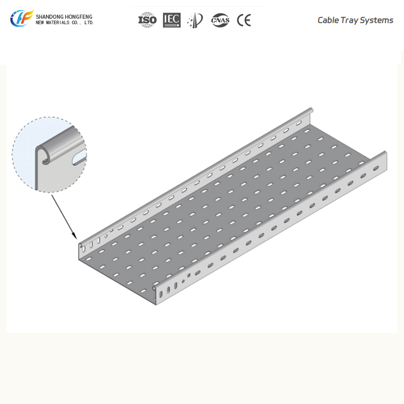
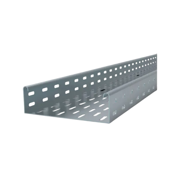
Perforated Cable Tray
Use when:
Medium cable load (typically < 50–70 kg/m)
Ventilation required to reduce heat buildup
Indoor environments with limited contamination
Limitations:
Not suitable for long spans or heavy-duty systems
Ladder Cable Tray
Use when:
High cable load (> 70 kg/m)
Span requirements exceed 2.5–3.0 meters
Heat dissipation is critical (power cables)
Engineering note:
Preferred solution for high load capacity and structural efficiency
Wire Mesh Cable Tray
Use when:
Frequent on-site routing adjustments
Low-voltage / data cable systems
Fast installation is required
Limitations:
Lower load capacity
Not suitable for long span or heavy-duty applications
Solid Bottom Cable Tray
Use when:
Full cable protection is required
EMC shielding or dust control is critical
Clean rooms or sensitive environments
Trade-off:
Limited ventilation → cable derating may be required
Load, Span & Deflection Control
Load Calculation Principles
Total load = cable weight + tray self-weight + safety factor
Typical safety factor: 1.5 – 2.0
Recommended design margin for future expansion: 20–30%
Design should be based on fully loaded conditions, not initial installation.
Span Selection Logic
Standard span range:
1.5 m / 2.0 m / 2.5 m / 3.0 m
General engineering guidance:
Light load → shorter span
Heavy load → reduced span or reinforced system
Deflection Requirement
Common engineering limits:
Standard projects: L/200
Higher specification projects: L/240 or stricter
Span and support spacing must be verified against load capacity curves.
Typical Reference (Conceptual Only)
Load Level Suggested Tray Type Typical Span
<50 kg/m Perforated 1.5–2.0 m
50–100 kg/m Ladder 2.0–2.5 m
>100 kg/m Ladder (heavy-duty) 2.5–3.0 m
Final values depend on manufacturer data and project requirements.
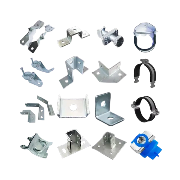
Support System Selection Logic
Support systems should be designed as part of the load-bearing system, not as independent components.
Installation Type
Suspended system → suitable for long, straight runs (industrial plants, rooftops)
Wall-mounted system → suitable for space-constrained areas
Support Type
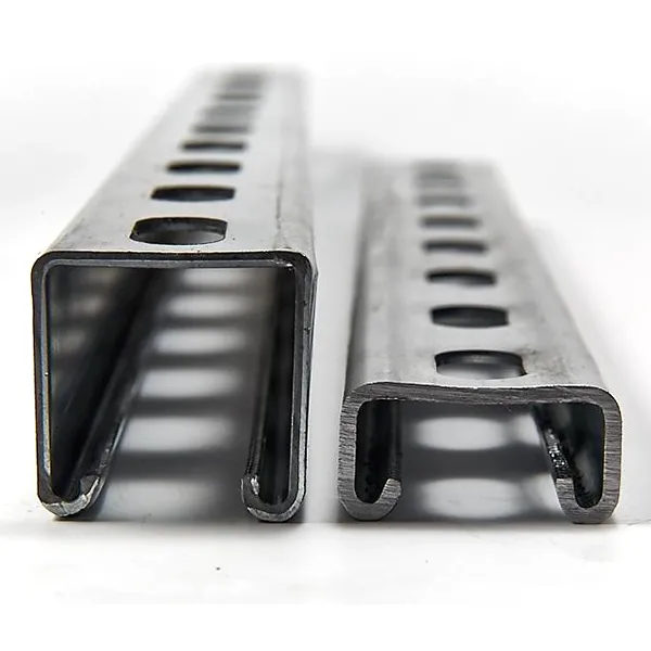
Strut channel system → standard load, flexible installation
Heavy-duty support → high load or long span applications
System Matching Consideration
Long span + high load → heavy-duty trapeze support
Short span + medium load → standard strut system
Wall-mounted systems → bracket spacing should follow span design
Support Spacing Rule
Support spacing is not fixed and must be determined based on:
Tray load capacity
Span design
Deflection limits
Routing & Directional Engineering
Elbows
Select horizontal or vertical elbows based on routing direction
Avoid sharp turns to reduce cable stress
Tee vs Cross
Tee → main route with single branch
Cross → multi-directional distribution (use only when necessary)
Minimize directional changes to reduce installation complexity.
Reducers
Used when cable density changes
Gradual reduction is recommended to maintain cable fill ratio
Engineering Practice
Fittings should be minimized where possible, typically within 15–20% of the total routing length.
Cable Fill Ratio Consideration
General Rule
Recommended fill ratio: ≤ 40–50%
Design considerations:
Heat dissipation
Future expansion
Maintenance accessibility
System design should reflect final cable conditions rather than initial installation status.
Protection and Safety Strategy
Protection measures should be applied based on environmental and operational conditions.
When to Use Covers
Outdoor installations
Dust or moisture environments
Fire Protection
Fire barriers at wall/floor penetration points
Common in tunnels, metro systems, and industrial plants
Cable Separation
Power and control cables should be separated
Dividers can be used to reduce electromagnetic interference
Grounding & Bonding Requirements
All metallic cable tray systems must maintain electrical continuity.
Key Requirements
Bonding jumpers required at expansion joints
Required where mechanical connections may interrupt continuity
Proper grounding ensures system safety and compliance with international standards (e.g., IEC / NEMA).
Common Engineering Mistakes to Avoid
Oversized span leading to excessive deflection
Ignoring future cable expansion
Incorrect tray type selection
Missing grounding continuity
Overfilled cable trays
Excessive fittings increasing system complexity
Engineering Scope Clarification
Cable tray system design typically involves:
Tray type selection
Load and span verification
Support system configuration
Routing and layout planning
For project-specific layouts, load calculations, and detailed drawings, further engineering evaluation is required.