
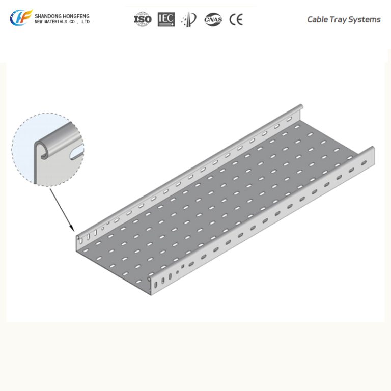
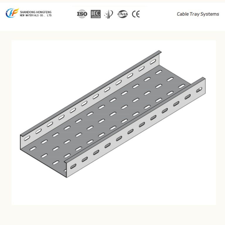
Perforated Cable Tray
Product Overview
Perforated Cable Tray Systems for Industrial and Infrastructure Cable Management
IEC 61537 Compliant
Available in Multiple Load Classes and Material Options
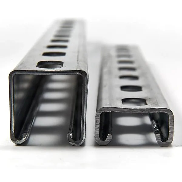
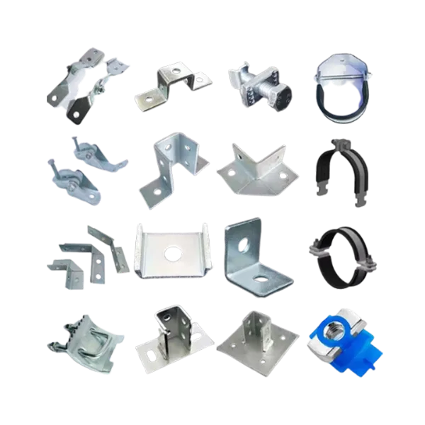
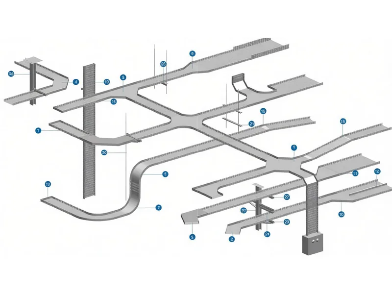
Compatible with Complete Cable Tray Support and Accessory Systems
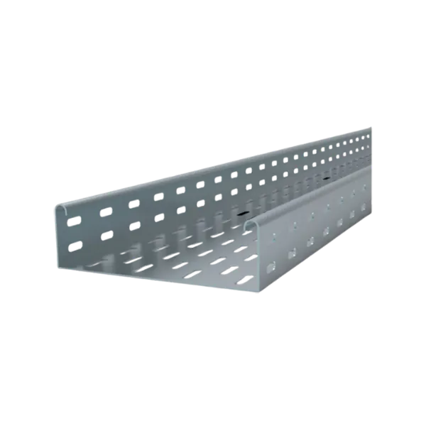
Perforated cable tray systems are designed for general-purpose cable routing in industrial, commercial and infrastructure applications. The perforated bottom structure provides cable ventilation while maintaining the mechanical strength required for typical power, control and instrumentation cable installations.
The system is available in multiple widths, side rail heights, material grades and surface finishes, and can be supplied together with compatible fittings, support systems and accessories.
System Characteristics
Structural and Functional Features
- Perforated bottom design for cable ventilation
- Suitable for power, control and instrumentation cable systems
- Available in GI, HDG, SS304 and SS316L materials
- Compatible with standard fittings, covers and support systems
- Multiple dimensions and load classes available
- Manufactured in accordance with IEC 61537
Common Applications
Designed for general industrial and commercial cable routing applications.
Typical Configuration
Width: 100–600 mm
Side Height: 50 / 75 / 100 mm
Thickness: 1.2 / 1.5 / 2.0 mm
Common Applications
Building MEP · Industrial Plants · Data Centers · Utility Installations
Designed for cable systems requiring higher structural load capacity.
Typical Configuration
Width: 200–1000 mm
Side Height: 100 / 150 mm
Thickness: 2.0 / 2.5 / 3.0 mm
Common Applications
Power Plants · Petrochemical Facilities · Mining · Heavy Industry
Designed for corrosive and hygienic operating environments.
Material Options
SS304
SS316L
Common Applications
Chemical Plants · Offshore Facilities · Marine Installations · Food Processing
Designed for installations requiring extended support spacing.
Typical Configuration
Recommended Span: 3–6 m
Side Height: 150–200 mm
Thickness: 2.5–3.0 mm
Common Applications
Utility Tunnels · Infrastructure Projects · Cable Corridors
Designed for light-load cable systems in commercial buildings and indoor installations.
Typical Configuration
Width: 50–300 mm
Side Height: 50 mm
Thickness: 0.8–1.2 mm
Common Applications
Commercial Buildings · Offices · Data Cabling Systems
Product Selection Reference
Typical Configuration Guide
| Configuration | Typical Application |
| Light Duty | Office and data cabling systems |
| Standard | General industrial and commercial projects |
| Heavy Duty | High-load industrial power cable systems |
| Long Span | Utility tunnels and large infrastructure projects |
| Stainless Steel | Corrosive or hygienic environments |
Configuration selection may vary according to project load requirements, installation environment and support spacing.
Technical Specifications
General Dimensions
| Item | Specification |
| Width | 25–1000 mm |
| Side Rail Height | 25–200 mm |
| Standard Length | 2000 / 2440 / 3000 / 6000 mm |
| Material Thickness | 0.7–3.0 mm |
Perforation Configuration
| Item | Specification |
| Slot Size | 9 × 25 mm |
| Pitch | 50 × 25 mm |
| Perforation Ratio | 18%–30% |
Load Performance
| Item | Specification |
| Standard | IEC 61537 |
| Test Span | 2.0 m |
| Deflection Limit | L/200 |
| Typical Safe Working Load | 30–350 kg/m |
Actual load performance depends on tray dimensions, material thickness and structural configuration.
Material and Surface Finish Options
Pre-galvanized Steel (GI)
Hot-dip Galvanized Steel (HDG)
Powder Coated Steel
Stainless Steel 304
Stainless Steel 316L
Ingress Protection
IP30 (without cover)
IP40 (with cover)
Typical Applications
Perforated cable tray systems are commonly used in:
- Industrial Manufacturing Facilities
- Commercial and Office Buildings
- Data Centers
- Power Plants and Substations
- Renewable Energy Projects
- Railway and Metro System
- Airports and Transportation Infrastructure
- Hospitals and Public Buildings
Related Cable Tray Systems
| Project Requirement | Recommended System |
| Frequent cable modifications | Wire Mesh Cable Tray |
| Heavy power cable installation | Cable Ladder System |
| General-purpose cable routing | Perforated Cable Tray |
| Enclosed or dust-sensitive environments | Solid Bottom Cable Tray |
Technical Documentation
The following engineering documents are available through the Engineering Support Center:
- Product Data Sheet
- Load and Span Tables
- CAD / BIM Drawings
- Installation Manual
- Material and Finish Information
- Test Reports and Certifications
Page Footer Note
Detailed technical information, project-specific configurations and additional engineering documentation can be provided according to project requirements.


