
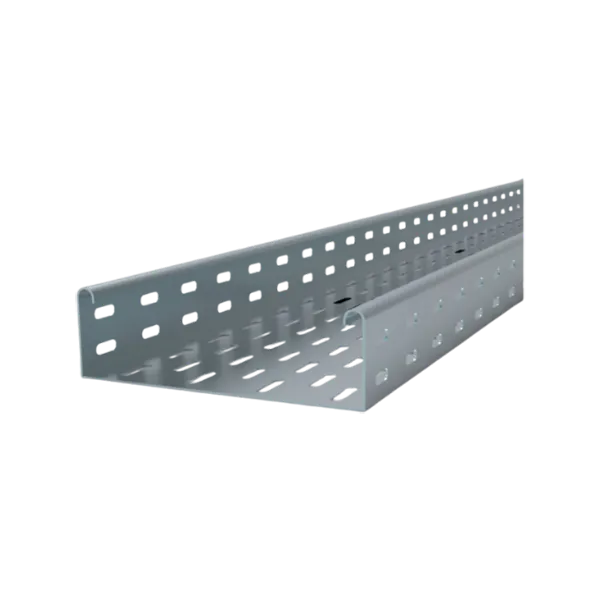
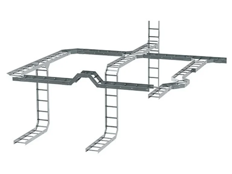
Ladder Cable Tray
Ladder Cable Tray Systems for Heavy-Duty Power Cable Support
IEC 61537 Compliant
Available in Multiple Load Classes and Material Options
Compatible with Complete Cable Tray Support and Accessory Systems
Ladder cable tray systems are designed for heavy-duty cable routing applications where high load capacity, long support spans, and maximum cable ventilation are required.
The open ladder structure provides superior heat dissipation for medium- and high-voltage power cables while maintaining excellent structural performance for industrial, infrastructure, and energy projects.
The system is available in multiple side rail profiles, dimensions, material grades, and corrosion protection finishes, and can be supplied together with compatible fittings, support systems, and accessories as a complete cable management solution.
Why Ladder Cable Tray?
Designed to solve heavy cable load and long-span installation challenges.
Ideal for Projects Requiring:
Heavy-duty power cable support
Long support spacing with reduced steel structures
Maximum cable ventilation and heat dissipation
Large-scale industrial cable routing
Outdoor and harsh-environment installations
Key Benefits
High load capacity for large cable volumes
Long span capability up to 6 meters
Maximum natural airflow
Reduced support structure requirements
Lower installation and lifecycle costs
Product Configurations
Description
Balanced solution for medium-load industrial applications where ladder systems are preferred over tray systems.
Typical Configuration
Width: 200–600 mm
Height: 100–150 mm
Thickness: 1.5–2.0 mm
Common Applications
Manufacturing Plants
Industrial Facilities
Utility Buildings
Description
Designed for high-current power transmission systems with large cable volumes and heavy load requirements.
Typical Configuration
Width: 400–1000 mm
Height: 150–200 mm
Rung Spacing: 250–300 mm
Thickness: 2.0–3.0 mm
Span: 3–6 m
Common Applications
Power Plant
Substations
Steel Mills
Cement Plants
Mining Facilities
Description
Engineered for projects requiring extended support spacing to reduce structural steel and installation costs.
Typical Configuration
Span: 4–6 m
Height: 150–200 mm
Reinforced Side Rails
Optional Return Flange Design
Common Applications
Infrastructure Projects
Pipe Racks
Industrial Corridors
Outdoor Installations
Description
Designed for aggressive environments where corrosion protection and service life are critical.
Material Options
Hot-Dip Galvanized Steel (HDG)
Stainless Steel 304
Stainless Steel 316L
Common Applications
Oil & Gas
Petrochemical Facilities
Offshore Platforms
Coastal Installations
Marine Environments
Description
Specialized ladder system for transportation and infrastructure projects requiring durability and accessibility.
Typical Configuration
Height: 100–150 mm
Anti-Corrosion Coating
Fire-Resistant Options Available
Common Applications
Metro Systems
Railways
Road Tunnels
Utility Tunnels
Underground Facilities
Description
Designed for vertical cable routing applications in shafts, risers, and utility cores.
Typical Configuration
Width: 100–400 mm
Special Vertical Fixing Brackets
High Structural Stability
Common Applications
High-Rise Buildings
Industrial Shafts
Utility Risers
Power Distribution Rooms

System Characteristics
Product Selection Reference
Typical Configuration Guide
| Project Requirement | Recommended System |
| General industrial power cables | Medium Duty Ladder |
| Heavy cable loads | Heavy Duty Ladder |
| Long support spans | Long Span Ladder |
| Corrosive environments | Corrosion Resistant Ladder |
| Tunnel and infrastructure projects | Tunnel Ladder |
| Vertical shafts and risers | Vertical Ladder |
Configuration selection may vary according to project load requirements, installation environment, cable type, and
support spacing.
Engineering Design Range
General Dimensions
| Item | Specification |
| Width | 100–1000 mm |
| Side Rail Height | 50–200 mm |
| Standard Length | 2000 / 3000 / 6000 mm |
| Side Rail Thickness | 1.5–3.0 mm |
| Rung Thickness | 1.2–2.5 mm |
| Rung Spacing | 150–300 mm |
Structural Configuration Side Rail Type C-Channel Profile Reinforced C-Channel Structural I-Beam Profile Rung Type
Tubular Rung Flat Perforated Rung
Load Performance
| Item | Specification |
| Standard | IEC 61537 |
| Test Span | 3–6 m |
| Deflection Limit | L/200 |
| Medium Duty Load | 150–300 kg/m |
| Heavy Duty Load | 300–600 kg/m |
Actual load performance depends on tray dimensions, side rail profile, thickness, and support spacing.
Material and Surface Finish Options
Pre-Galvanized Steel (GI) Hot-Dip Galvanized Steel (HDG) Powder Coated Steel Stainless Steel 304 Stainless Steel 316L
Ingress Protection IP00 – Open Ladder Structure (IP protection is generally not applicable due to ladder configuration.)
Typical Applications
Ladder cable tray systems are commonly used in:
Power Generation Facilities
Substations and Transmission Projects
Oil & Gas Facilities
Petrochemical Plants
Mining Operations
Heavy Manufacturing Plants
Utility Tunnels
Railway and Metro Systems
Renewable Energy Projects
Large Infrastructure Projects
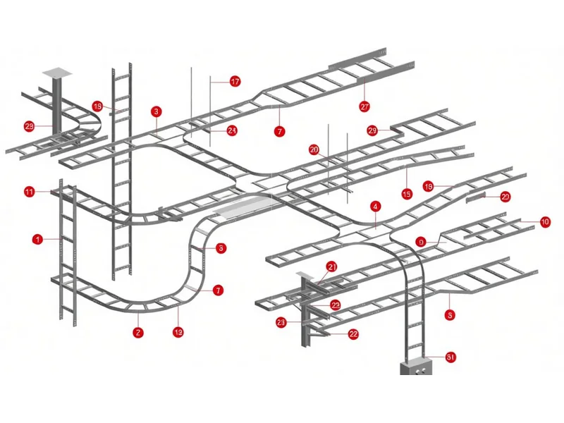
Complete Cable Management System
Compatible with:
Horizontal Elbows
Vertical Bends
Tees
Crosses
Reducers
Covers
Splice Plates
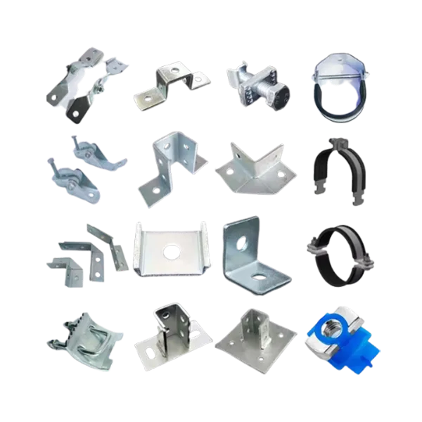
Hold-Down Clamps
Support Brackets
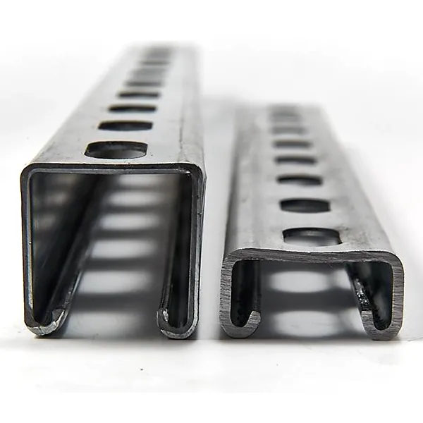
Strut Channel Framing Systems
Ceiling Suspended Supports
Wall-Mounted Supports
Heavy-Duty Support Structures
Related Cable Tray Systems
| Project Requirement | Recommended System |
| Heavy power cable installation | Ladder Cable Tray |
| General-purpose cable routing | Perforated Cable Tray |
| Frequent cable modifications | Wire Mesh Cable Tray |
| Dust-sensitive environments | Solid Bottom Cable Tray |
Proven in Industrial and Infrastructure Projects
Ladder cable tray systems have been supplied for:
Power Generation Projects
Hydrogen and Ammonia Facilities
Petrochemical Plants
Metro and Railway Systems
Mining and Heavy Industry Projects
Large Industrial Manufacturing Facilities
View Project References →
Technical Documentation
The following engineering documents are available through the Engineering Support Center:
Product Data Sheet
Load and Span Tables
CAD Drawings
BIM Models
Installation Manual
Material and Finish Information
Test Reports
Compliance Certificates
Technical Documentation →
Engineering Support →
Engineering Support
Our engineering team can provide:
Cable Tray System Design Support
Load Calculation Assistance
Span Optimization
Corrosion Protection Recommendations
Project-Specific Customization
Tender and Specification Support
Contact Technical Team →
Page Footer Note
Detailed technical information, project-specific configurations, load calculations, and engineering documentation can be provided according to project requirements.